Electric motors quietly power modern life, from electric vehicles and factory robots to ceiling fans and precision pumps. In 2026, the leading designs are judged by efficiency, torque, noise, thermal control, service life, and intelligent control. Yet no single motor wins every application. A compact permanent magnet motor may deliver excellent power density, while an induction motor can offer durable performance with fewer rare-earth materials. The right choice depends on speed, load, operating temperature, maintenance access, and cost.
So, how does an electric motor convert electrical energy into motion? The answer begins with electromagnetism. Current flows through coils, creating a magnetic field around the stator. This field interacts with magnets or induced magnetic forces in the rotor. Attraction and repulsion produce torque, turning the shaft that drives a wheel, fan, pump, or machine tool. In a workshop, the effect becomes tangible: a small motor starts humming, its shaft accelerates, and electrical input becomes controlled rotation. Sensors and electronic controllers now adjust that rotation within milliseconds. They can improve efficiency, reduce vibration, and protect the motor from overheating. Still, real systems lose energy through resistance, friction, sound, and heat. That detail is easy to overlook. This guide examines top electric motor technologies, their internal components, practical strengths, and everyday limitations. It also questions common efficiency claims, because laboratory results may not reflect dusty factories, steep roads, or changing loads. Understanding those differences leads to safer, more reliable motor decisions.
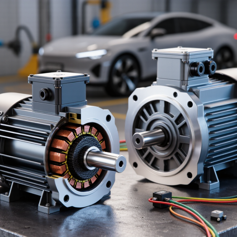
Electric motors create motion by turning electrical energy into electromagnetic force. Current flows through stator windings, producing a rotating magnetic field. That field interacts with the rotor and creates torque. The shaft then drives a pump, fan, conveyor, or compressor. Simple in principle, but efficiency depends on operating conditions.
IEC 60034-30-1 defines efficiency classes for specific motor types and operating conditions. IE3 means Premium Efficiency, while IE4 indicates Super Premium Efficiency. IE5 represents Ultra Premium Efficiency, with lower declared losses under the standard’s test conditions. These classes help engineers compare motors more reliably. They do not guarantee identical savings in every installation. Load, voltage, cooling, bearing condition, and variable-speed operation still matter. A motor may carry an IE5 label and perform poorly when oversized or poorly controlled.
Tips: Check the motor’s rated load before choosing an efficiency class. Measure operating hours and actual load patterns. A qualified technician should verify compatibility with the drive and power system. Keep shafts aligned and cooling paths clean. Small maintenance errors create measurable heat.
In practical projects, IE4 or IE5 can reduce wasted energy during long operating cycles. However, the highest class is not automatically the best purchase. Initial cost, control equipment, duty cycle, and available space deserve careful review. Field measurements are often more useful than assumptions. Some specifications also need closer reading. The test standard and motor application must match.
2026 Top Electric Motors: How Do They Create Motion?
Electric motors create motion through the Lorentz force. A current-carrying conductor sits inside a magnetic field. The field pushes the conductor sideways. This force acts at a distance from the rotor’s center, creating torque. In simple terms, greater current usually produces greater force. Stronger magnetic flux can also increase torque. The force direction depends on both current direction and magnetic-field direction.
Inside a motor, magnetic flux crosses the air gap between the stator and rotor. Current flows through carefully arranged windings. Their interaction produces repeated pushing forces around the rotor. Electronic control changes current timing, keeping the torque moving in one direction. However, the basic equation, F = BIL, is only an ideal model. Real motors lose energy through resistance, heat, vibration, and imperfect magnetic paths. More current can help, but excessive current may cause overheating or magnetic saturation.
Tips: Check the air gap, winding temperature, and operating current during testing. Listen for unusual vibration. Small changes matter. Engineers should compare measured torque with calculated torque, then question every difference. The model may be wrong for the real machine.
| Motor Type | How Motion Is Created | Primary Magnetic Field Source | Torque Relationship | Current Behavior | Typical Strengths | Typical Limitations |
|---|---|---|---|---|---|---|
| Brushed DC Motor | Current-carrying rotor conductors experience a magnetic force. A commutator reverses rotor current at the correct position so torque remains in the same rotational direction. | Permanent magnets or a wound stator field. | T ≈ ktI under normal operation; torque is approximately proportional to armature current. | Current is mechanically switched through the rotor windings. | Simple control, high starting torque, and straightforward speed adjustment. | Brush and commutator wear, electrical arcing, acoustic noise, and maintenance requirements. |
| Brushless DC Motor | An electronic inverter energizes stator phases in sequence. The rotating stator magnetic field attracts or repels the permanent-magnet rotor. | Permanent magnets on the rotor and controlled current in the stator. | T ≈ ktI; torque depends on phase current and the alignment of the rotor flux with the stator field. | Electronic commutation controls the magnitude, timing, and direction of phase current. | High efficiency, low mechanical wear, compact size, and good dynamic response. | Requires an inverter and rotor-position information or sensorless estimation. |
| Permanent-Magnet Synchronous Motor | The inverter creates a rotating stator field that synchronizes with the permanent-magnet rotor. Torque is produced by the interaction of rotor and stator magnetic flux. | Permanent-magnet rotor plus energized stator windings. | For a simplified surface-magnet design, T ∝ ψriq, where ψr is rotor flux linkage and iq is torque-producing current. | Vector control separates current into flux-producing and torque-producing components. | High power density, strong efficiency, and precise speed and torque control. | Permanent magnets add cost and may suffer irreversible demagnetization if overheated or over-stressed. |
| Induction Motor | A rotating stator field induces rotor current through electromagnetic induction. The interaction between rotor current and magnetic flux creates torque. | AC current in the stator; the rotor field is induced rather than supplied through brushes. | Torque depends on air-gap flux, rotor current, rotor resistance, and slip; no slip means no induced rotor current in the ideal case. | Stator current contains magnetizing and torque-producing components. Rotor current frequency increases with slip. | Rugged construction, low maintenance, and suitability for many industrial loads. | Lower power factor at light load, inrush current, and variable-speed operation usually requires an inverter. |
| Synchronous Reluctance Motor | The rotor moves toward the position of minimum magnetic reluctance as the stator’s rotating field changes its preferred flux path. | Controlled stator current and rotor saliency; the rotor normally has no windings or permanent magnets. | Torque is related to inductance difference: T ∝ (Ld − Lq)i2 in a simplified model. | Requires coordinated multiphase current to maintain rotor-field alignment. | No rotor magnets, low rotor electrical losses, and good high-speed potential. | Torque ripple, acoustic noise, and inverter-dependent starting and control. |
| Switched Reluctance Motor | Stator phases are switched on in sequence. The toothed rotor is pulled toward the energized stator pole with the lowest magnetic reluctance. | Pulsed stator current and a salient, iron-only rotor. | A simplified expression is T = ½i2(dL/dθ), where inductance changes with rotor position. | Current is applied in discrete phase pulses based on rotor position. | Robust rotor, high-temperature tolerance, and no rotor windings or permanent magnets. | Torque ripple, audible noise, and the need for specialized current control. |
| Concept | Equation | Meaning | Units | How It Produces Motion |
|---|---|---|---|---|
| Lorentz Force on a Charge | F = q(v × B) | A moving electric charge experiences a force perpendicular to its velocity and the magnetic field. | F in newtons, q in coulombs, v in m/s, B in teslas. | The force deflects charge motion; in motor conductors, the combined forces create a turning moment. |
| Force on a Current-Carrying Conductor | F = BIL sinθ | A conductor of length L carrying current I experiences force in magnetic flux density B. | F in newtons, B in teslas, I in amperes, L in meters. | The force is greatest when the conductor is perpendicular to the magnetic field, where θ = 90°. |
| Magnetic Flux | Φ = BA cosθ | The amount of magnetic field passing through an area A. | Φ in webers, B in teslas, A in square meters. | Changing flux linkage induces voltage and helps establish the electromagnetic interaction between rotor and stator. |
| Torque of a Current-Carrying Coil | τ = NBIA sinθ | A coil with N turns and area A experiences torque in magnetic field B when current I flows. | τ in newton-meters, N dimensionless, I in amperes. | Motor geometry and commutation or electronic control keep the torque-producing component positive over each rotation. |
| Mechanical Output Power | P = τω | Mechanical power equals torque multiplied by angular velocity. | P in watts, τ in newton-meters, ω in radians per second. | For a given power, increasing speed reduces required torque, while increasing torque raises the available load-driving force. |
| Electrical-to-Mechanical Efficiency | η = Pout/Pin × 100% | The fraction of electrical input power converted into mechanical output power. | Percentage. | Losses include winding resistance, magnetic hysteresis, eddy currents, bearing friction, windage, and inverter losses. |
Note: Equations shown are standard simplified relationships. Actual torque depends on motor geometry, air-gap flux, winding distribution, saturation, temperature, operating speed, and control strategy.
2026 Top Electric Motors: How Do They Create Motion?
Electric motors create motion by converting electrical energy into controlled magnetic force. Inside the stator, alternating current creates magnetic fields around fixed windings. These fields shift around the stator in a repeating sequence. The rotating field crosses the narrow air gap and reaches the rotor. A small air gap matters. It strengthens the magnetic interaction but requires careful manufacturing.
Field speed follows the synchronous-speed equation, nₛ = 120f/p. Here, nₛ is speed in revolutions per minute, f is frequency in hertz, and p is the pole count. A 60 Hz motor with four poles has a synchronous speed of 1,800 rpm. Increasing frequency raises speed. Increasing pole count lowers it. Technicians compare calculated speed with measured shaft speed. Measurements beat assumptions.
The rotor responds to the moving stator field and develops torque. In an induction motor, relative motion induces current in the rotor conductors. That current creates its own magnetic field, pulling the rotor forward. The rotor must remain slightly slower than nₛ. This difference is called slip. No slip, no induction torque. The ideal equation is clean, but real motors are not. Friction, heat, voltage imbalance, and load changes alter performance. A useful inspection checks current, temperature, vibration, and actual speed together. One reading can mislead.
2026 Top Electric Motors: How Do They Create Motion?
Electric motors turn electrical energy into torque through magnetic fields. The stator creates a rotating field, while the rotor responds through attraction, induction, or magnetic alignment. Demand is rising sharply. The International Energy Agency’s Global EV Outlook 2025 reported more than 17 million electric car sales worldwide in 2024. Motor efficiency now affects range, cooling, material use, and lifetime cost.
PMSMs use permanent magnets and usually deliver high power density, strong efficiency, and smooth torque. Their weakness is material dependence and possible demagnetization under severe heat. Induction motors avoid permanent magnets and offer rugged construction, reliable field weakening, and strong overload tolerance. However, rotor currents create heat, which can reduce efficiency during demanding cycles. The U.S. Department of Energy estimates motor systems consume about 69% of industrial electricity in the United States. Small losses become expensive at scale.
BLDC motors use electronic commutation and commonly suit compact tools, pumps, and light mobility systems. They are efficient, but torque ripple and acoustic noise can require careful control. Switched-reluctance motors use a simple rotor without magnets or windings. They tolerate high temperatures and reduce dependence on critical magnetic materials. Noise and torque pulsation remain difficult engineering problems. There is no universal winner. A high-speed traction drive may favor PMSM, while a hot, cost-sensitive machine may expose its advantages. That judgment still deserves testing.
Comparing PMSM, induction, BLDC, and switched-reluctance motor designs by representative peak efficiency.
Electric motors create motion by producing torque from the interaction between magnetic fields in the stator and rotor. PMSM and BLDC motors use permanent magnets, induction motors create rotor current through electromagnetic induction, and switched-reluctance motors pull their toothed rotor toward the energized stator poles. The values shown are representative peak-efficiency levels found in common industrial and transportation-oriented designs; actual results vary with motor size, speed, control strategy, cooling, and operating load.
An electric motor converts electromagnetic force into shaft rotation. Current enters the stator windings, creating a rotating magnetic field. The rotor follows that field and produces torque. A high output rating alone proves little. The International Energy Agency reports that motor-driven systems use about 53% of global electricity (Energy Efficiency 2017). Small efficiency losses can therefore become significant operating costs.
Efficiency should be checked across the real load profile, not only at rated output. A motor running at 40% load may perform differently from its nameplate promise. Power density also needs careful comparison. Measure kilowatts per kilogram at the same duty, cooling method, and speed. Otherwise, a compact motor may only appear superior. Peak numbers can mislead.
Speed affects torque, noise, gearing, and control requirements. Higher speed may reduce motor size, but it can increase bearing stress and cooling demand. Thermal limits are equally practical. A winding operating near its insulation limit may shorten service life, especially inside a dusty cabinet. IEC 60034-30-1 provides efficiency-class definitions, while U.S. Department of Energy motor-system assessments emphasize the large industrial energy impact of motor operation. I would record casing temperature, current, vibration, and output during several hours of testing. One short laboratory reading is not enough. Real installations remain messier.
They convert electrical energy into rotating shaft motion. Current creates a magnetic field inside the stator. The rotor follows it and produces torque.
They are efficiency classes for defined motor types and test conditions. IE3 means Premium Efficiency. IE4 and IE5 indicate progressively lower declared losses.
No. Load, voltage, cooling, and control settings affect actual savings. An oversized motor can waste energy, despite its high efficiency label.
Check performance across the real load pattern, not only at rated output. Record current, output, casing temperature, and vibration for several hours. One reading is weak evidence.
A motor operating at 40% load may perform differently from its nameplate rating. Measure actual demand before selecting an efficiency class.
No. Compare power density using the same speed, cooling method, and duty cycle. A smaller casing may hide higher heat or lower performance.
Higher speed can reduce motor size. It may also increase bearing stress, noise, cooling demand, and gearing requirements. Faster is not always better.
Keep shafts aligned and cooling paths clean. Check bearings, cabinet dust, temperature, and vibration. Small mistakes create measurable heat. I may still overlook something.
Review purchase cost, operating hours, control equipment, duty cycle, and available space. The highest class may not provide the quickest return. Field measurements deserve more trust than assumptions.
In 2026, electric motors are increasingly defined by performance, efficiency, and thermal reliability, with IEC 60034-30-1 efficiency classes IE3, IE4, and IE5 providing a clear framework for comparison. This overview explains how does an electric motor convert electrical energy into motion by using current to create magnetic fields and torque. Through the Lorentz force, magnetic flux interacts with conductors, producing the rotational force required to drive a load.
The motion process begins when the stator generates a rotating magnetic field. This field induces or attracts rotor movement, creating torque and continuous rotation. The synchronous speed is described by nₛ = 120f/p, linking frequency and pole count to operating speed. PMSM, induction, BLDC, and switched-reluctance motors use different methods to generate and control torque. Their practical performance is evaluated through efficiency, power density, speed range, and thermal limits, helping engineers select the right design for demanding applications.

RedCat Motors