Top 10 Electric Motor Types How Do They Work?

Time:2026-10-03 Author:Oliver
0%

What is an electric motor and how does it work? This question supports nearly every modern machine, from a quiet cooling fan to a heavy industrial pump. An electric motor converts electrical energy into mechanical motion. Stephen J. Chapman, author of Electric Machinery Fundamentals, explains, “An electric motor is a device that converts electrical energy into mechanical energy.” The process sounds simple, but motor design involves magnetic fields, current control, heat, friction, and load demands.

The International Energy Agency has reported that electric motor systems consume roughly half of the world’s electricity. That figure shows why motor selection matters. The U.S. Department of Energy also identifies motor-driven equipment as a major energy-use category in industrial facilities. Small efficiency gains can therefore produce visible savings on a factory energy meter. Sometimes, the difference is surprisingly practical.

This guide examines ten major electric motor types, including brushed DC, brushless DC, induction, synchronous, stepper, servo, switched reluctance, universal, hysteresis, and permanent-magnet motors. Each type creates torque differently. Some rely on slip between magnetic fields. Others depend on electronic switching or precise feedback. A stepper motor may move a camera lens in measured increments, while an induction motor can drive a conveyor for years with limited maintenance. Yet no design is perfect. Efficiency, starting torque, speed control, cost, noise, and operating temperature can change the best choice. The following overview connects technical theory with real equipment, while recognizing that simplified explanations can hide important engineering trade-offs.
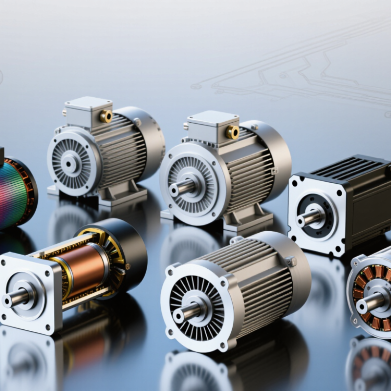
Top 10 Electric Motor Types How Do They Work?

Electric Motor Fundamentals: Parts, Motion, and Energy Conversion

An electric motor converts electrical energy into mechanical motion through magnetic force. Its main parts are the stator, rotor, windings, shaft, bearings, and housing. The stator creates a magnetic field, while the rotor responds inside it. The shaft carries this rotation to a fan, pump, wheel, or gearbox.

The process begins when current enters the windings. In a brushed DC motor, a commutator switches current mechanically. In a brushless motor, electronic controls perform that timing. An induction motor creates rotor current through electromagnetic induction, while a synchronous motor follows the rotating magnetic field more precisely. Stepper motors move in measured angles. Reluctance motors use changing magnetic resistance. The categories overlap more than simple charts suggest.

Motion depends on torque, current, magnetic strength, and load. More current usually produces more torque, but it also creates heat in the copper windings. I check temperature, vibration, and sound during practical testing. A warm bearing can reveal alignment problems before failure becomes obvious. Small errors matter. Efficiency compares useful mechanical output with electrical input, yet real losses include friction, resistance, air drag, and switching heat. Motor selection is not only about speed. Starting torque, duty cycle, cooling, and control accuracy can change the result. I have found that a motor may perform well unloaded but struggle badly under a steady, heavy load. That detail deserves attention.

Top 10 Electric Motor Types: Typical Efficiency Ranges

Electric motors convert electrical energy into mechanical motion through magnetic fields. The chart compares representative peak-efficiency ranges; actual performance varies with motor size, load, speed, control method, and operating conditions.

How to read the chart: Higher efficiency means less electrical energy is lost as heat during operation. Permanent-magnet and electronically controlled motors commonly achieve the highest efficiency, while universal and stepper motors generally trade efficiency for cost, torque, or positioning capability.

How Electric Motors Create Torque and Continuous Rotation

Top 10 Electric Motor Types: How Do They Work?

Electric motors create torque when magnetic fields push or pull against each other. The stator produces a magnetic field, while the rotor responds and turns. This interaction converts electrical energy into continuous mechanical rotation. Torque rises when current increases, although heat and winding resistance limit safe operation.

The ten common motor types include brushed DC, brushless DC, induction, synchronous, permanent-magnet synchronous, switched-reluctance, stepper, universal, servo, and hysteresis motors. Brushed motors use mechanical commutators to switch current. Brushless and synchronous designs use electronic control or alternating currents to maintain rotation. Induction motors create rotor current through electromagnetic slip. Reluctance motors follow the path of lowest magnetic resistance.

Rotation must keep renewing itself. A controller changes current timing, or the alternating field moves around the stator. In a stepper motor, this movement occurs in measured magnetic steps. A servo motor combines feedback with rapid corrections, making its position more precise. Small timing errors matter.

Practical testing reveals an uncomfortable detail. A motor may produce strong starting torque but perform poorly at speed. Load, friction, voltage, cooling, and alignment all change the result. Simple formulas help, but they cannot replace measurement. A temperature probe, current reading, and vibration check often explain more than a perfect calculation. Real motors are not perfectly tidy.

Top 10 Electric Motor Types: How Do They Work? — How Electric Motors Create Torque and Continuous Rotation

No. Motor Type Operating Principle How Torque Is Created Continuous Rotation Typical Control Method Main Advantages Common Limitations Typical Applications
1 Brushed DC Motor Electromagnetic DC motor Current flows through armature windings in a magnetic field. The interaction between the current-carrying conductors and the field produces electromagnetic force and shaft torque. A commutator and carbon brushes mechanically reverse the armature current as the rotor turns, maintaining torque in the same rotational direction. Variable DC voltage, PWM, or an H-bridge for reversing direction. Simple control, high starting torque, low initial system complexity. Brush and commutator wear, electrical arcing, audible noise, and regular maintenance requirements. Small machinery, pumps, actuators, toys, automotive accessories, and battery-powered equipment.
2 Brushless DC Motor Permanent-magnet synchronous motor Permanent magnets on the rotor interact with a rotating magnetic field generated by electronically switched stator windings. Electronic commutation energizes the stator phases in sequence according to rotor position, producing continuous synchronous rotation. Three-phase inverter with Hall sensors, encoders, or sensorless position estimation. High power-to-weight ratio, good efficiency, long service life, and low mechanical maintenance. Requires electronic control hardware; torque ripple and acoustic noise can occur with basic commutation. Drones, fans, power tools, electric mobility systems, appliances, and robotics.
3 Permanent-Magnet Synchronous Motor Sinusoidally controlled synchronous motor Permanent-magnet rotor flux interacts with a smoothly rotating stator magnetic field. Reluctance torque may also contribute when the rotor has saliency. The rotor locks to the rotating stator field and turns at synchronous speed, with speed determined mainly by electrical frequency and pole count. Field-oriented control using a variable-frequency inverter and rotor-position feedback or estimation. High efficiency, high torque density, precise speed regulation, and strong low-speed performance. Permanent magnets increase cost and may suffer demagnetization at excessive temperature or fault current. Traction drives, industrial servos, compressors, machine tools, and high-efficiency pumps.
4 Squirrel-Cage Induction Motor Asynchronous AC motor AC current creates a rotating magnetic field in the stator. Relative motion induces current in the rotor bars, and the interaction of rotor current with the magnetic field produces torque. The rotor continuously follows the rotating field but must operate with some slip, meaning its speed is slightly below synchronous speed under load. Direct-on-line starting, soft starter, or variable-frequency drive. Rugged construction, low maintenance, reliable operation, and broad industrial availability. Starting current can be high; efficiency and power factor vary with load, and speed control requires an inverter. Conveyors, fans, pumps, compressors, machine tools, and general industrial drives.
5 Wound-Rotor Induction Motor Slip-ring asynchronous motor A rotating stator field induces current in a wound rotor. External rotor resistance can alter the current and torque characteristics during starting. Continuous rotation is produced through induction, with operating speed remaining below synchronous speed because of slip. Rotor-resistance control, soft starter, or variable-frequency drive. High starting torque and controllable starting current for heavy mechanical loads. Slip rings and brushes require maintenance; external resistors create power losses and additional heat. Cranes, hoists, elevators, crushers, mills, and high-inertia industrial equipment.
6 Synchronous Reluctance Motor Salient-pole synchronous motor The rotor moves toward the position of lowest magnetic reluctance, aligning its preferred magnetic axis with the rotating stator field. After synchronization, the rotor rotates at synchronous speed without rotor windings or permanent magnets. Variable-frequency inverter, commonly with field-oriented control and a starting algorithm. No rotor magnets or rotor windings, low rotor losses, good efficiency, and high-temperature capability. Usually needs an inverter; torque ripple, noise, and lower power factor can require careful design. Pumps, fans, compressors, conveyors, and energy-efficient industrial drives.
7 Switched Reluctance Motor Electronically commutated reluctance motor Independently energized stator phases create magnetic attraction that pulls the salient rotor toward alignment with the active stator poles. Electronic switching energizes successive phase windings, repeatedly advancing the rotor around the stator. Position-sensitive power converter using a rotor sensor or sensorless estimation. Simple and robust rotor, high-speed capability, strong fault tolerance, and no permanent magnets. Torque ripple, acoustic noise, electromagnetic interference, and complex control design. Pumps, compressors, appliances, automotive auxiliaries, and harsh-environment drives.
8 Universal Motor Series-wound commutator motor The field winding and armature winding are connected in series. Reversing the supply reverses current in both windings, so the torque direction remains unchanged. A commutator mechanically switches armature current, allowing operation from either AC or DC supplies with continuous rotation. Voltage control, phase-angle control, or electronic speed control. Very high starting torque, high power-to-weight ratio, and high operating speed. Brush wear, noise, arcing, electromagnetic interference, and reduced efficiency at light load. Handheld tools, vacuum cleaners, mixers, blenders, and other compact high-speed appliances.
9 Permanent-Magnet Stepper Motor Discrete-position synchronous motor Sequentially energized stator phases attract or repel permanent-magnet rotor poles, moving the rotor between stable angular positions. Continuous rotation is possible when the controller applies phase currents in a repeating sequence; each command advances the rotor by a defined step angle. Pulse-and-direction driver, full-step, half-step, or microstepping control. Accurate open-loop positioning, high holding torque, and straightforward digital control. Can lose synchronism under overload, has torque that decreases with speed, and may produce vibration or resonance. Printers, scanners, laboratory instruments, valve actuators, and light-duty positioning systems.
10 Hysteresis Motor Self-starting synchronous motor A rotating stator field magnetizes a high-retentivity rotor. Magnetic hysteresis causes the rotor field to lag the stator field, producing torque. Once synchronized, the rotor rotates at synchronous speed and maintains continuous rotation with very low speed variation. Usually connected directly to a fixed-frequency AC supply; an inverter may be used for variable-speed operation. Quiet operation, smooth torque, reliable synchronization, and nearly constant speed. Relatively low efficiency and limited output power compared with many modern motor technologies. Timing devices, low-power synchronous drives, audio equipment, and precision instruments.

Ten Major Electric Motor Types and Their Operating Principles

A practical guide to electric motors begins with how current creates torque. A brushed DC motor sends current through a commutator and brushes into a rotating armature. Magnetic attraction and repulsion turn the shaft, while brush wear remains a maintenance concern. A brushless DC motor replaces mechanical switching with electronic commutation. Position sensors, or sensorless control, energize stator coils in sequence. It runs efficiently, but its controller is not optional.

An induction motor uses alternating current to create a rotating stator field. That field induces rotor current, producing torque without direct electrical contact. Slip is essential, because the rotor must lag slightly behind the field. A wound-field synchronous motor uses direct-current rotor excitation and locks rotor speed to supply frequency. A synchronous-reluctance motor follows the lowest magnetic-reluctance path. Its rotor has shaped iron sections and no windings. A switched-reluctance motor energizes separate stator poles, pulling a toothed rotor into alignment. It is robust, although torque ripple and acoustic noise can be difficult.

A stepper motor advances through fixed magnetic steps. It offers simple positioning, but missed steps can occur under overload. A universal motor uses series-connected windings and works with alternating or direct current. It delivers high starting torque but can be loud. A hysteresis motor relies on magnetic lag in a hardened rotor, giving smooth, quiet synchronous motion. A linear motor unfolds the rotary structure, creating direct thrust along a track. Selection depends on load, speed, heat, control accuracy, and duty cycle. Practical testing often reveals that catalog ratings rarely match dusty, variable machines.

Comparing Motor Designs by Speed, Torque, Control, and Efficiency

Top 10 Electric Motor Types: How Do They Work?

Motor selection changes with speed, torque, control, and efficiency. The International Energy Agency reports that motor-driven systems consume over half of global electricity. The U.S. Department of Energy estimates they use about 70% of industrial electricity. That choice matters.

Brushed DC motors deliver strong starting torque and simple speed control, but brushes wear. Brushless DC and permanent-magnet synchronous motors provide high efficiency, fast response, and accurate electronic control.

Induction motors remain rugged and affordable, although high-performance control usually requires an inverter. Synchronous-reluctance motors reduce rotor losses, while switched-reluctance motors tolerate heat and overloads. Their torque ripple can create noise.

Universal motors reach very high speeds but require maintenance. Servo motors combine feedback with precise torque and position control. Stepper motors offer simple positioning, yet their torque falls sharply at high speed. Linear motors produce direct motion without gears.

Torque comes first. A conveyor may need steady torque at low speed, while a spindle needs smooth high-speed operation. IEC 60034-30-1 efficiency classifications help compare motor losses, but laboratory ratings rarely represent a complete drive system. Cables, inverters, cooling, and partial-load operation change actual performance. A motor can look efficient on paper. Not always. Field measurements often reveal poor sizing, excessive cycling, or an oversized safety margin. The comparison is useful, but imperfect; real machines still demand testing under their actual load.

Choosing the Right Electric Motor for Different Applications

Choosing the right electric motor starts with the application, not the motor’s popularity. An induction motor suits pumps, fans, and conveyors because it is durable and relatively simple. A synchronous motor supports steady speed and improved efficiency under controlled conditions. Brushless DC motors work well in compact equipment requiring quiet operation and precise speed control. Stepper motors provide predictable movement, but they may lose position under excessive load. Servo motors offer feedback, fast correction, and accurate positioning.

Tips: Define torque, speed, duty cycle, voltage, space, noise, and environmental conditions before choosing. Check starting torque, not only rated power. A motor that looks efficient on paper may perform poorly with frequent starts. Allow space for cooling, wiring, and maintenance access. Small details matter.

Match the motor to the load profile. A conveyor carrying heavy boxes needs reliable starting torque, while a robotic joint needs feedback and rapid response. For wet or dusty areas, enclosure protection deserves careful attention. Gear reduction can improve torque, although it adds cost, weight, and possible backlash. I would avoid selecting a motor from horsepower alone. That shortcut often creates overheating, vibration, or unnecessary energy use. Real installations are imperfect; alignment, ambient heat, and changing loads can alter performance. Test the motor with the actual controller and load whenever possible. A practical trial may reveal problems that calculations miss.

FAQS

How does a brushed DC motor create rotation?

Current passes through brushes and a commutator into the rotating armature. Magnetic attraction and repulsion turn the shaft. Brush wear requires regular maintenance.

What makes a brushless DC motor different?

Electronic switching energizes stator coils in sequence. Position sensors or sensorless control guide this process. The controller is essential.

Why does an induction motor need slip?

Alternating current creates a rotating magnetic field in the stator. The rotor must lag slightly behind this field. That difference induces rotor current and produces torque.

When is a synchronous motor useful?

It maintains speed according to the supply frequency. Direct-current rotor excitation creates a locked magnetic relationship. It suits applications needing steady speed and controlled efficiency.

What are the main limitations of stepper motors?

Stepper motors move through fixed magnetic steps. They provide predictable positioning under suitable loads. Excessive load can cause missed steps.Small details matter.

Which motor types suit conveyors, pumps, and fans?

Induction motors often suit these applications because they are durable and relatively simple. Selection still depends on starting torque, duty cycle, heat, and speed.

Why should motor selection consider the complete load profile?

A conveyor carrying heavy boxes needs dependable starting torque. A robotic joint may need feedback and rapid correction. Rated power alone can mislead.

What should be checked before installing an electric motor?

Check torque, speed, voltage, duty cycle, available space, noise, and surroundings. Allow room for cooling, wiring, and maintenance. Wet or dusty areas need suitable enclosure protection.

Can gear reduction improve motor performance?

Gear reduction can increase output torque and adapt speed. It also adds weight, cost, and possible backlash. The improvement is not always worth the trade-off.

Why should a motor be tested with its actual controller and load?

Catalog ratings may not match dusty machines or changing workloads. Alignment, ambient heat, vibration, and frequent starts can alter performance. Real testing often reveals problems that calculations miss. I would not trust paper specifications alone.

Conclusion

Electric motors convert electrical energy into mechanical motion by using magnetic fields to create force. But what is an electric motor and how does it work? In simple terms, current flowing through coils interacts with magnetic fields, producing torque that turns a rotor inside a stationary part called the stator. This interaction is carefully controlled to maintain continuous rotation, allowing motors to power machines, tools, appliances, vehicles, and industrial equipment.

The article introduces ten major electric motor types and explains their operating principles, including how their construction, current supply, and control methods affect performance. It also compares motor designs by speed, starting torque, efficiency, precision, maintenance needs, and controllability. By understanding these differences, readers can choose a suitable motor for specific applications, whether the priority is smooth movement, high torque, energy savings, compact size, or reliable long-term operation.

Oliver

Oliver

Oliver is a seasoned marketing professional with a wealth of expertise in driving brand awareness and engagement. With a deep understanding of our company's product offerings, he consistently delivers high-quality content that enriches our professional blog. His insights not only shed light on......